
Tracking or Guiding? What’s The Difference?
One of the first things I recall asking was “what’s the difference between tracking and guiding?”
Although the answer can be as complicated as we choose to make it, fundamentally-speaking, the answer is actually quite simple; tracking is when the mount relies solely on its internal mechanics and gearing to keep its rotation counter to that of the earth, whereas guiding uses software to achieve this by use of being locked onto a star and using this to achieve more precise movement and countermovement.
Although both of these depend greatly on how good the mechanical aspects are, with guiding you can achieve much longer exposures at longer focal lengths in order to gather that greater amount of detail.
There are pros and cons for tracking and guiding respectively, and the route you go is entirely up to you, but it’s always good to have both options available. For example, if “seeing” isn’t that great on a night, this can affect how well the guiding works, whereas tracking isn’t affected by this at all.
Either way, both require you to setup the mount as well as possible, ie levelling, balancing and polar alignment, all of which I cover further on.
Step-by-step
I use several pieces of software for successful guiding. There are quite a few options for this but it all comes down to personal preference. I use Astrophotography Tool (APT), PHD2, Stellarium, Stellarium Scope, Sharpcap, TeamViewer and Synscan.
1. The first thing to do is balance the mount and OTA in both RA and Dec as perfectly as possible. This is done in order to reduce the amount of stress on the mount gears, as this may affect its ability to track, which will affect the length of exposures you can successfully take. It’s handy to have things a little “east heavy” as this helps to reduce backlash in the gears as well, helping them to mesh together and make for smoother tracking/guiding.
2. Point the mount (not the OTA) towards approximately celestial North and then level it. Most mounts come with a bubble level fitted now and whilst not perfectly accurate, I find it’s sufficient for my requirements. You can also use a spirit level and check that way. However that usually involves removing the mount from the tripod. For me, the bubble level is enough.
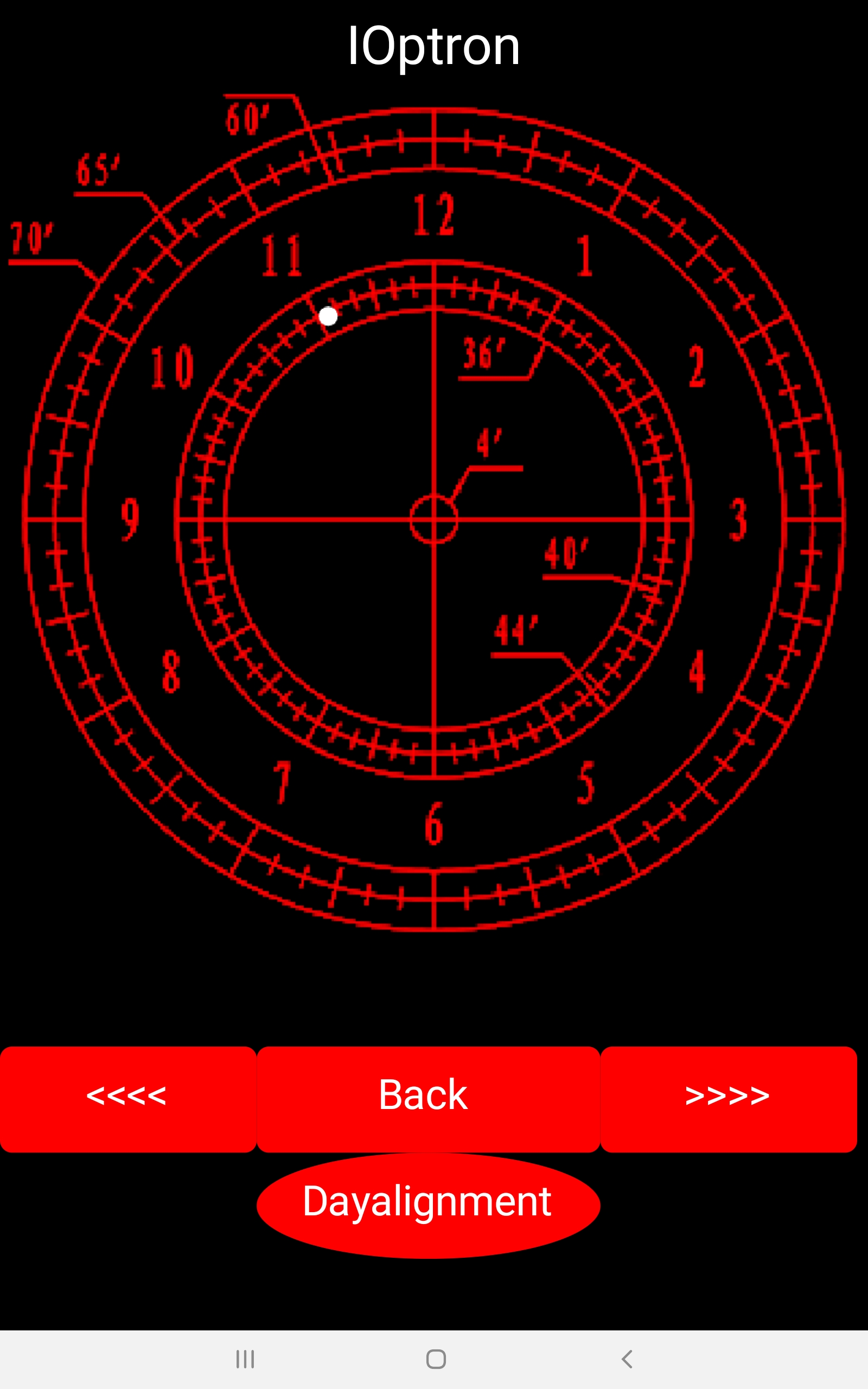
3. Polar align the mount. If you’re shooting wide field then a rough alignment can often suffice. The more accurate the alignment though, the more it helps with longer exposures. A lot of mounts are fitted with a polar scope for this exact thing. Again these are perfectly adequate, but they’re not as precise as they could be. In order to make sure that even the rough alignment is precise I use the Polar Alignment Pro app on my phone in order to obtain the correct hour angle of Polaris.
So I get a rough alignment this way and then use the polar alignment tool in Sharpcap to get it more precise. I can definitely recommend this method as it’s quick and highly accurate.
Open Sharpcap and from the “Cameras” menu, select your guidecam, in my case the ZWO ASI 120mm. Once it’s connected, set the exposure time to around 2 to 3 seconds and then navigate to the “Tools” menu, and then select Polar Alignment. This is where the previous rough alignment using the polar scope is handy. The more accurate that was, the easier Sharpcap will be able to platesolve. There should be around 15 stars on screen, although I’ve personally managed with only 5. The camera can pick up hot pixels too though, so if this happens just increase the noise reduction value.
Yellow boxes around the stars are the ones used to platesolve the image. Once platesolving has succeeded the status will change to “solved.”
Now that the first frame has been solved, you need to rotate the RA axis. Don’t do this until you’ve pressed “Next” though, otherwise you end up having to start again. Unlock the RA clutch and rotate through a full 90 degrees. Apparently it doesn’t matter in which direction, but I personally go counter clockwise. Sharpcap carries on in the meantime attempting to platesolve. Once this has been done, and Sharpcap knows you’ve rotated the full 90 degrees, it will then display the “Next” button again, along with the “Solved” message. There may be times when it’s not able to solve the image. Initially try rotating the RA axis a little further. If this doesn’t work then go back to the start and adjust your exposure settings.
Assuming everything has worked as it should so far, you should see one of the brighter stars highlighted in yellow with an arrow pointing to a nearby target. At this point you ONLY need to adjust the attitude and azimuth bolts on the mount to move the indicated star onto the target. What this does is line up the mount’s RA axis with the North Celestial Pole (NCP.) As you make small adjustments you will eventually get the star close to the target area, and when you’re very close the arrow and target change to a set of parallel lines which then need to be brought together. Once they’re as close as possible, you’re aligned.

Close the camera and exit Sharpcap. RETURN THE MOUNT TO THE HOME POSITION! I can’t stress that enough. I was in a brain fog moment the one night and forgot that part. Consequently when I told the mount to go to my target that evening, I had a scope/mount collision at maximum slew rate and ended up having to strip the mount to repair the damage. It could have been much worse though so I count myself lucky.
4. Because I use APT with external software, I open them in a specific order. I’m not sure if I have to do it like that or not, but I prefer the satisfaction of seeing in the log that APT has confirmed it’s connection to the software. So I fire up in this sequence;
a) Synscan. Once opened, select “Connect” and restore previous hibernation data.
b) PHD2. Once opened I connect the guidecam and the mount. For my setup I find that an exposure time of 1.5 seconds at 90 gain and 2x noise reduction will get me the best results. Once connected I press “Begin Looping” at the bottom of the main page.
c) Stellarium Scope. Mine is setup to connect to the mount and to automatically fire up the main Stellarium program.

d) APT. When opening, APT will, assuming you’ve told it previously that you use PHD2 and Stellarium, automatically connect to these. It will also connect to the mount and imaging camera, again if you’ve previously set these parameters. If you’re using a different camera than the last time you used APT then press the SHIFT button as you press CONNECT and you can then select your camera.
At this point I will go to the “Camera” tab and enable “Live View” keeping my exposures sub 5 seconds at unity gain. For my imaging camera, the ZWO ASI178MC, this is around 200, although there’s apparently no actual unity gain for the ASI178 according to ZWO. I’ll also select “Auto Stretch Left” on the histogram.
Switching back to the “Gear” tab, I’ll open up the “Point craft” button and then go to “Objects” at the top. From there I go to “Stars” and double click “Polaris.” At that point I will select “Blind.” What you’ve just done is tell APT where you think you’re pointing and asked it to platesolve the image. Now this CAN take up to 3 minutes. Personally if it takes more than 60 seconds then I try again. I also unpark the mount at this point and you can either do this within APT itself or using Synscan.
But once it’s platesolved the image, it’ll give you the exact coordinates of where you’re pointing. Hit the “Sync” button on the still-open Point craft window. This will synchronise the platesolved image to the mount. I’ll also press the other “Sync” button, which fires the platesolved coordinates to Stellarium.
I’m now ready to tell APT where I want to image tonight. So let’s say, for the sake of argument, that I want to image the Iris Nebula in the constellation Cepheus. I go to the “Objects” button in the “Gear” tab (not the one on the still-open Pointcraft window), navigate to “Deep Sky” and in the search bar type “Iris.” Double click that. Then press “Goto.” The mount will slew to where it thinks the Iris Nebula is. In the Pointcraft window, goto “Objects”, and double click the Iris Nebula. Press “Blind” and let it platesolve. Once it’s done that and it shows you in the next section below the results from the platesolving, press “Sync” and it will update the mount’s position from where it thinks it is to where it actually is. At this point I go back into the “Objects” list (not the Pointcraft one) and double click Iris Nebula again. I then press “Goto” and the mount should then get on target and start using PHD2 to guide. Because there’s a connection between APT and PHD2, in APT on the left you should see “PHD2 State” and altering numbers which are the corrections to keep the guidestar locked in PHD2. You can check on PHD2 manually as well to make sure the graph is looking good.

I then go back to the “Camera” tab in APT and do some test exposures to absolutely confirm I’m on target. Usually I’ll see the target on screen from a single exposure. Once I’ve confirmed that, then I run the imaging plan I’ve selected.
Now if I’m planning on staying out with the rig I don’t bother with this part, but if I’m going inside and leaving it I’ll fire up TeamViewer and connect to the laptop with my tablet. This means that I can go in, watch a film, have a coffee, or whatever and still monitor what’s going on with the mount.
PHD2 Calibration
There maybe times when PHD2 needs to recalibrate to the mount, for example if you’ve changed guidecam, or stripped it down etc. I’ve copied the method of carrying out a calibration from the online guide.
Conventional Mounts
Two things need to be measured by PHD2 as part of guider calibration:
- The angle of the camera relative to the telescope axes
- The length of the guide pulse needed to move the telescope by a specific amount
PHD2 handles these measurements automatically by sending guide pulses to the mount and watching how far and in which direction the star moves between guide camera images. This process begins after you have selected a star and then clicked on the PHD2/Guide icon button. Yellow cross-hairs will appear over the original location of your guide star and PHD2 will start to move the mount in various directions, tracking how the star moves as a function of what move commands were sent to the mount. The status bar will display the commands as they are sent to the mount, along with the incremental movements of the guide star relative to its starting position. PHD2 will do this on both axes, first moving east and west, then north and south. PHD2 wants to move the star up to 25 pixels in each direction in order to get an accurate calibration. Once this is complete, the crosshairs will turn green and guiding will start automatically.
Although PHD2 moves the guide star in all four directions, only the west and north movements are actually used to compute the guide rates and camera angle. The east and south moves are used only to restore the star roughly to its starting position. Before the north moves are begun, you will see a sequence of pulses that are intended to clear backlash. PHD2 takes only a moderate approach to clearing this backlash, watching for a clear pattern of movement in a single direction with no reversals. If your mount has a large amount of Dec backlash or you’re guiding at a long focal length in poor seeing conditions, this phase of calibration may not remove all the backlash. Your best option for avoiding this problem is to make sure the last move of the mount prior to the calibration is north. You can accomplish this with a short slew or by using the hand-controller to get the mount moving north as evidenced by obvious movement of the guide star in the PHD2 display. If the backlash is not cleared adequately, the computed declination rate may be too low. You may also see that the south pulses leave the guide star well-short of its starting position – this is another visual clue that you have significant declination backlash in your mount. If you see evidence of sizable backlash, you can run the Guiding Assistant tool and measure it directly.
In most cases, calibration will complete automatically without any user involvement. If the mount doesn’t move sufficiently in the west or north directions, you will get an alert saying the calibration has “failed”. Failures of ths type are pretty uncommon but they can occur if some part of the hardware is simply not working (e.g. a bad guide cable). Unless you see a “failed” message, the calibration actually completed. You may see other alert messages advising you that the calibration results look suspect or show mount behavior that is likely to cause problems during guiding. These are advisory messages only, they don’t mean that the calibration itself failed.
If you’re using an ASCOM (or Indi) connection for either the ‘mount’ or ‘aux-mount’, a good calibration can be re-used for a long time, and that is the preferred way to operate. These connection options allow PHD2 to know where the telescope is pointing, so a calibration done at one point in the sky will be automatically adjusted as you slew to different targets. The old method of having to re-calibrate whenever you slewed the scope or switched the side-of-pier is a thing of the past so long as PHD2 has pointing information. With this type of set-up, you would only re-calibrate if you rotate the position of the guide camera by more than a few degrees or make other major changes to the hardware configuration. In general, the best practice is to get a good calibration within about +/- 20 degrees of the celestrial equator and high enough in the sky to avoid major seeing (turbulence) problems. If you chose ‘auto-restore calibration’ when you built your profile or chose that option in the Guiding tab of the Advanced Dialog, you can simply connect to your gear, choose a guide star, then begin guiding immediately. Beginners will probably have better success if they do a fresh calibration at the start of each night’s session. Finally, if you’re using an instrument rotator as part of your equipment profile, PHD2 can use the ‘Rotator’ connection to adjust the calibration data based on the angular position of the guide camera – one less reason for re-doing a calibration.
You can always review the results of your last calibration by using the ‘Tools’ menu and clicking on ‘Review Calibration Data’ That will open a dialog that shows a graphical representation of the mount’s movements along with the values that were computed for guiding your mount. As a quick quality check, you can open this window and confirm that 1) the RA and Dec lines are roughly perpendicular and 2) the plotted points are roughly linear with no significant curves, bends, clumping of points, or reversals in direction. If you do see these kinds of odd patterns in the graph, you should probably re-do the calibration. Even with high-end mounts, calibrations can occasionally go awry because of environmental conditions, especially wind and bad seeing.
After a calibration is completed, PHD2 will “sanity check” the results to be sure the calculations at least look reasonable. If they don’t, you will see an advisory message at the top of the main window that describes the calibration result that looks questionable. You can choose to ignore the alert or click on ‘Details’ to get more information. It is generally advisable to pay attention to these alerts because there is no point in trying to guide using a significantly bad calibration.

[…] Guiding Walkthrough […]
LikeLike
[…] Guiding Walkthrough […]
LikeLike